Multitouch Table
Project Specification
posted on 2011-04-05 by Lance Castillo
Project Charter
Project Overview:
This project entails building a multi-touch surface using a LCD TV. Multi-touch technology allows programmers to create interactive graphical user interfaces that are more natural to use.
Project Approach:
The LCD TV will be surrounded by IR LED’s and use Frustrated Total Internal Reflection technology to send data to a modified webcam that detects infrared light. The webcam will send its data to TUIO’s reacTIVision optical tracker to sense when a person touches the screen. So far as I know, there will be four people on this team, myself included. I will be the project leader and James will be our mentor and team liaison. Helper #1 will be both a secretary and a project builder. Helper #2 will be both a treasurer and project builder as well.
Project Objectives:
Our milestones include disassembling the LCD TV, building the frame to hold the entire assemblage together, creating the IR LED array assembly, final project assembly, and testing. Deliverables are as follows. Helper #1 as secretary will document our weekly meetings and assemble a weekly outline of what was accomplished. Helper #1 will also be in charge of assembling the IR LED array which should be delivered by 4/25/11. Helper #2 will be in charge of building the frame that will hold all the internals of the mutli-touch surface which should be delivered by 5/9/11. As treasurer, Helper #2 will also be in charge of ordering the major parts for our project which should be done by 4/8/11. I will help with every stage of the project to ensure that each of our milestones are met in a timely fashion and to ensure that everything goes as smoothly as possible.
Constraints, Risk and Feasibility:
One potential stumbling block has to do with the FFC cable coming from the LCD TV. If it is too short, then we will have to buy an extension cable. Realistically, by the end of the quarter, we should have a working FTIR multi-touch system. That doesn’t mean that the frame will be done or that it will look pretty or anything like that. It might just be a skeleton of what it should be, but it should work.
Group Management
Major Roles:
Major roles include the team mentor and liaison, team leader, treasurer, secretary, and project builder. The team mentor/ liaison is in charge of overseeing decisions that the leader makes and scheduling time for the entire group to meet on a weekly basis to work on the project. The team leader is in charge of the two helpers that have been promised. The team leader is also in charge of overseeing each step in the manufacturing process to ensure that everything comes together smoothly at the end. The treasurer is in charge of ordering the major parts that the project requires as well as keeping track of the budget. The secretary is in charge of documenting weekly meetings and submitting a weekly outline of what was accomplished. The team leader will submit the final weekly report. Everyone in the team is technically a project builder and will do their part to work on assembling the final product. Decisions will be made by the leader and mentor. Our main communication will be though email. I might setup a Google group so that we can keep all our correspondence in one place. If the main components are not coming together by a certain time frame, then I will know that the schedule is slipping. At that point I, as the team leader, will dedicate as much time as I can to the project so that we can catch up with where we should be.
Project Development
There is both a software side and a hardware side to this project. I will be handling the software side on my own, since it doesn’t require much extra work. Most, if not all the work is going to come from assembling the hardware components correctly. The rest of the team will help out with the hardware and I will be devoting a lot of my time in this area as well. As for the software, we will be using TUIO’s reacTIVision optical tracker to detect when a multi-touch event has occurred. For hardware, we require an LCD TV, a webcam with an IR filter, IR LED’s, and the components that we need to build a frame.
The LCD TV will be donated for our use and the rest of the components will have to be bought. The webcam can be bought for around $35. An IR filter costs around $5, depending on where you buy it. The IR LED’s can be bought for $1.99 a piece. The rest of the cost is going to come from the frame which could cost anywhere from $25-$75 total for parts to build it from. The webcam is an essential part of the project since without it, reacTIVision would not have any input to act on. We can get the webcam from Amazon. The IR LED’s are also a major component of the project since reacTIVision senses blobs of IR light and turns them in to touch data. The IR LED’s can be bought from Radio Shack. Another major component is the IR filter since reacTIVision only deals with the IR spectrum. Passing the program visible light would not produce any useful touch data. There is a website called peauproductions.com that sells the IR filter we need. The frame is needed to hold the entire assembly together and make it easy for transportation. We can by the parts for it at Home Depot or any similar location. If we order the parts we need from online by 4/8/11, then they should arrive within the next two weeks.
Testing will be accomplished using TUIO’s reacTIVision software. If we can get the tell-tale white blobs of IR light to show up, then the multi-touch setup is complete. At that point we could concentrate on the frame if it still needs to be built. Further testing can be done by actually running a piece of multi-touch software such as Open Exhibit’s multi-touch core, which uses Flash. We can document the entire process by taking snapshots of each of the milestones as they are being achieved. Then we could compile a document at the end explaining each milestone and showing the pictures of what was done.
Project Schedule
Top level milestones include ordering parts, disassembling the LCD TV, building the frame to hold the entire assemblage together, creating the IR LED array assembly, modifying the webcam, final project assembly, and testing. Ordering parts means finalizing the parts list and making the final purchases online. I expect that to be done by the end of this week (4/8/11). Disassembling the LCD TV includes taking the TV out of its housing so that IR light can pass though the screen more easily. We will know if this is done properly when the webcam can detect IR light shining through the LCD screen. I expect that to be done by 4/18/11. Building the frame means measuring the LCD screen and building a frame around it that has space below for the webcam. We will know this is done when the LCD screen fits in the frame properly and that the webcam is positioned properly. I expect this to be done by 5/9/11. Creating the IR LED assembly entails connecting the IR LED’s to a frame that will surround the LCD TV screen. It also entails powering the LED’s. We will know this is done when the reacTIVision software recognizes input from the IR LED array. I expect that to be finished by 4/25/11. Modifying the webcam means removing the IR blocker from the webcam and replacing it with a high pass IR filter that blocks visible light. We will know that this is finished when reacTIVision recognizes the IR input that the webcam is giving it. I expect that to be done by 4/25/11. Final assembly includes making sure all the components work together. We will know that this is finished when we have a finished multi-touch table that can sense when the surface of the LED TV is touched. I expect this to be done by 5/16/11. Testing means developing a mini program that uses the touch data that the table outputs. We will know when this is done when the program properly uses the touch data that the table sends it. I expect that to be finished by 5/23/11. Necessary weekly milestones include compiling the weekly report and documenting our work. One last hopeful milestone is to actually develop a more substantial program that showcases what our multi-touch table can do.
Week 2 Update
posted on 2011-04-12 by Lance Castillo
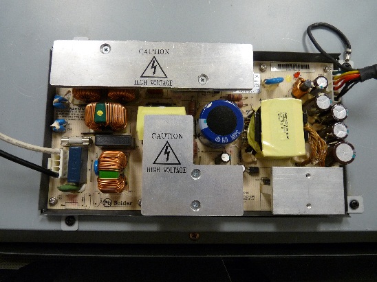
James acquired a LCD televistion that we could use for our Multitouch Table display. The power source did not work and we were given a replacement power source to install into the TV.
It turns out that the power source that we were given was the wrong model, so a new one has been ordered. Here is a picure of the broken power source on the TV:
Week 3 Update
posted on 2011-04-20 by Lance Castillo
We ordered parts the Monday before last or at least we thought we had. We sent in our order in two forms, though the TIES website and via email to the person ordering the parts. We were very specific and we provided all the information that was needed to order the parts including links to the websites selling them. The list for this project was relatively short. All I ordered were the IR LED’s, the webcam, and the visible light filter. The mixup was taken care of by this Monday and the parts were ordered.
Milestone Report
posted on 2011-04-20 by Lance Castillo
Final list of project team members:
- Lance Castillo
- Brian Harrington
- Wesley Hsu (Honorary Member)
These are the milstones from the Project Specification:
| Order | Name | Expected Date of Completion |
| 1 | Order Parts | 4/8/11 |
| 2 | Disasemble TV | 4/18/11 |
| 3 | Create IR LED Assembly | 4/25/11 |
| 4 | Modify Webcam | 4/25/11 |
| 5 | Create Frame | 5/9/11 |
| 6 | Final Assembly | 5/16/11 |
| 7 | Software Testing | 5/23/11 |
Here are the new Milestones and the reasons for changing them:
| Order | Name | Expected Date of Completion | Reason for Changing | ||
| 1 | Order Parts | 4/18/11 | Our parts were ordered late becasue of a mixup with upper management. | ||
| 2 | Create Frame | 4/24/11 | Our parts haven’t come in yet, so we’ve decided to do what we can for now. | ||
| 3 | Disasemble TV | 5/14/11 | The TV’s new power supply came in on time. Since we know the TV is working we can now concentrate on it. | ||
| 4 | Modify Webcam | 5/14/11 | The parts haven’t come in yet. | ||
| 5 | Create IR LED Assembly | 5/14/11 | The parts haven’t come in yet. | ||
| 6 | Final Assembly | 5/28/11 | We are behind schedule. | ||
| 7 | Software Testing | 5/28/11 | We are behind schedule. | ||
These are each member’s responisbilities:
| Lance Castillo | |||
| Milestone: | Inluded Mini-Milestones: | ||
| Create Frame | Get Parts, Find Tools | ||
| Disasemble TV | Find Tutorial, Separate Into Components, Mount Components on Frame | ||
| Modify Webcam | Remove IR Filter, Insert New Visible Light Filter, Test on IR LED | ||
| Final Assembly | Mount Webcam to Frame, Mount IR LED Assembly to Frame | ||
| Testing | Install ReacTIVision Software, Make Adjustments to Components, Test Simple Multi-touch Program | ||
| Brian Harrington | |||
| Milestone: | Inluded Mini-Milestones: | ||
| Order Parts | None | ||
| Create IR Assembly | Arrange Lights in Ring Around LCD Screen, Mount to a Frame, Solder IR Lights Together | ||
| Final Assembly | Mount Webcam to Frame, Mount IR LED Assembly to Frame | ||
| Testing | Install ReacTIVision Software, Make Adjustments to Components, Test Simple Multi-touch Program | ||
| Wesley Hsu | |||
| Milestone: | Inluded Mini-Milestones: | ||
| Create Frame | Get Parts, Find Tools | ||
| Disasemble TV | Find Tutorial, Separate Into Components, Mount Components on Frame | ||
| Testing | Install ReacTIVision Software, Make Adjustments to Components, Test Simple Multi-touch Program | ||
Week 4 and 5 Update
posted on 2011-05-02 by Lance Castillo
We got a ton of work done these past two weeks. Here’s the breakdown of what was done:
- Disassembled TV down to its bare components
- Built a rudimentary frame to hold the multi-touch table
- Modified the webcam to see only the 890nm Infra Red light spectrum
This is what we want to do this upcoming week:
- Research prices on Acrylic sheets for the table
- Assemble the IR LED array
Some fun photos of what we’ve done:

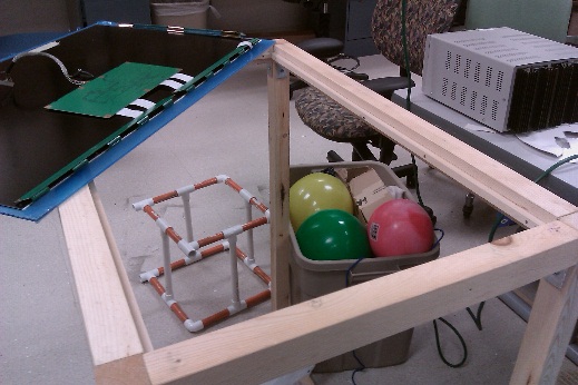
Bulding Materials that we used to create the table
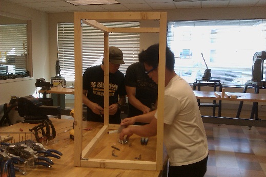
Building the frame in the MAE design lab

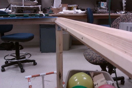
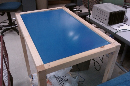
Finished frame
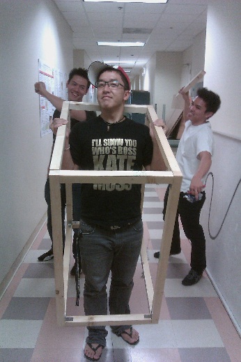
Fun with the finished frame
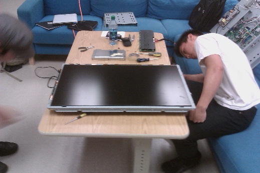
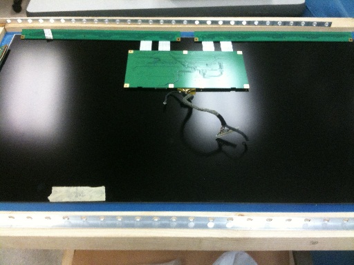
Starting to dismanlte the LCD matrix components
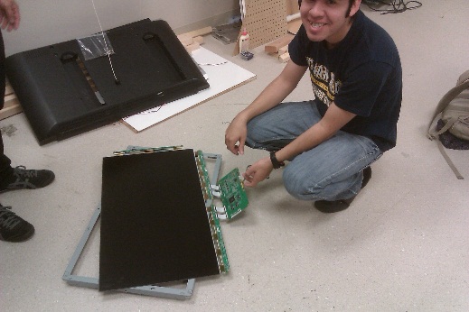
The LCD matrix
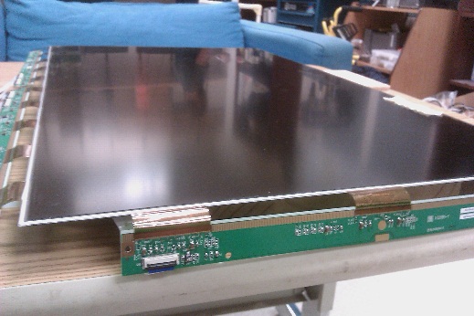
Close-up of the matrix
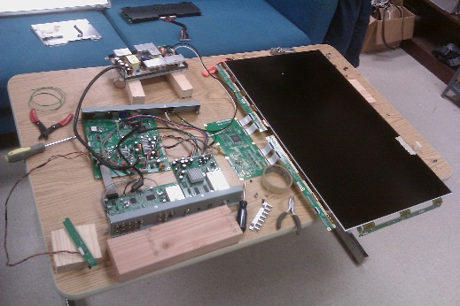
Re-assembled TV components test
Wesley’s laptop clock showing on the LCD matrix
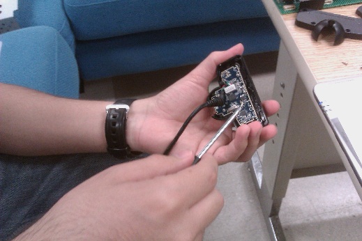
Taking apart the PS3 Eye to remove the filter and add the one we bought
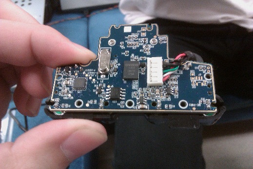
Close-up of PS3 Eye circuit board
Week 6 and 7 Update
posted on 2011-05-16 by Lance Castillo
Here’s what we got done in the past two weeks:
- Replaced the flimsy angle brackets with sturdier ones and glued everything in place
- Recieved the order of LED’s
- Bought the 3/8 inch and 1/4 inch acrylic for the top and bottom of the table
- Bought the resistors for the LED array assembly
- Bought a bread board to test the assembly before we actually solder it together
Here’s what we want to get done in the next couple of weeks:
- Cut the acrylic down to size
- Sand and polish the sides of the acrylic
- Solder the LED array together
- Buy an aluminum frame for the LED array to go in
Pictures Coming Soon!
Final Milestone Report
posted on 2011-05-16 by Lance Castillo
Final list of project team members:
- Lance Castillo
- Brian Harrington
- Wesley Hsu (Honorary Member)
- Kevin Nguyen (Honorary Member)
These are the milstones from the last Milestone Report:
| Order | Name | Expected Date of Completion |
| 1 | Order Parts | 4/18/11 |
| 3 | Disasemble TV | 5/14/11 |
| 4 | Create IR LED Assembly | 5/14/11 |
| 5 | Modify Webcam | 5/14/11 |
| 2 | Create Frame | 4/24/11 |
| 6 | Final Assembly | 5/28/11 |
| 7 | Software Testing | 5/28/11 |
Here are the changed Milestones and the reasons for changing them:
| Milestones | Name | Expected Date of Completion | Reason for Changing | ||
| 1 | Create IR LED Assembly | 5/22/11 | We had to re-order the LED’s becasue they were ordered from Sweden and were taking forever to arrive. But they are here and we will work on them this week. | ||
These are each member’s responisbilities:
| Lance Castillo | |||
| Milestone: | Inluded Mini-Milestones: | ||
| Create Frame | Get Parts, Find Tools | ||
| Disasemble TV | Find Tutorial, Separate Into Components, Mount Components on Frame | ||
| Modify Webcam | Remove IR Filter, Insert New Visible Light Filter, Test on IR LED | ||
| Final Assembly | Mount Webcam to Frame, Mount IR LED Assembly to Frame | ||
| Testing | Install ReacTIVision Software, Make Adjustments to Components, Test Simple Multi-touch Program | ||
| Brian Harrington | |||
| Milestone: | Inluded Mini-Milestones: | ||
| Order Parts | None | ||
| Create IR Assembly | Arrange Lights in Ring Around LCD Screen, Mount to a Frame, Solder IR Lights Together | ||
| Final Assembly | Mount Webcam to Frame, Mount IR LED Assembly to Frame | ||
| Testing | Install ReacTIVision Software, Make Adjustments to Components, Test Simple Multi-touch Program | ||
| Wesley Hsu | |||
| Milestone: | Inluded Mini-Milestones: | ||
| Create Frame | Get Parts, Find Tools | ||
| Disasemble TV | Find Tutorial, Separate Into Components, Mount Components on Frame | ||
| Modify Webcam | Remove IR Filter, Insert New Visible Light Filter, Test on IR LED | ||
| Final Assembly | Mount Webcam to Frame, Mount IR LED Assembly to Frame | ||
| Testing | Install ReacTIVision Software, Make Adjustments to Components, Test Simple Multi-touch Program | ||
| Kevin Nguyen | |||
| Milestone: | Inluded Mini-Milestones: | ||
| Create Frame | Get Parts, Find Tools | ||
| Disasemble TV | Find Tutorial, Separate Into Components, Mount Components on Frame | ||
| Modify Webcam | Remove IR Filter, Insert New Visible Light Filter, Test on IR LED | ||
| Final Assembly | Cut acrylic down to size | ||
| Testing | Install ReacTIVision Software, Make Adjustments to Components, Test Simple Multi-touch Program | ||
Week 8 Update
posted on 2011-05-23 by Lance Castillo
We got a surprising amount of work done this week for the table. Here’s the rundown:
- Added an inner ledge to the wood frame to hold the LCD Matrix and Acrylic in place
- Drilled the aluminum LED frame so we can start the LED assembly
- Started soldering some of the LED’s together
Inner Ledge
Inner Ledge Clos-up
Bottom Layer of Acrylic Sitting in Inner Ledge
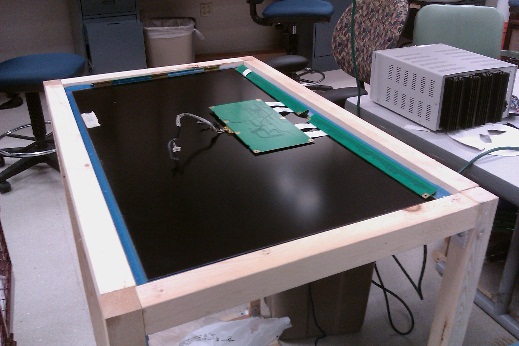
LCD Matrix Sitting on top of Acrylic
Aluminum LED Frame Before Drilling
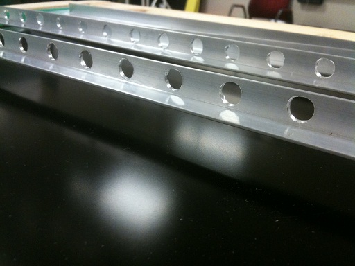
Aluminum Frame After Drilling
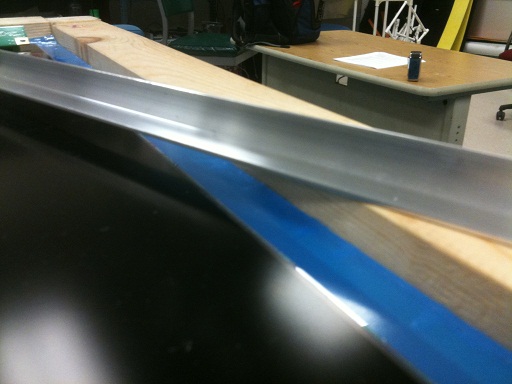
Aluminum Frame Placement
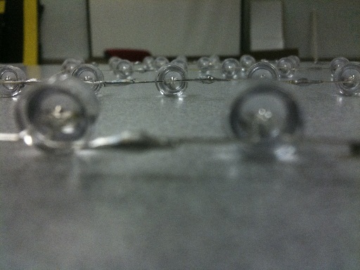
Soldered LED Close-up
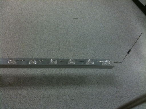
LED Assembly
Week 9 Update
posted on 2011-05-31 by Lance Castillo
Here’s what we got done this week and into the weekend:
- Finished soldering the LED arrays
- Tested the LED arrays to make sure they were working
- Cut the top and bottom layer of acrylic down to size
- Polished the sides of the top layer of acrylic to allow the FTIR effect
- Re-soldered the backlight so that the wires could reach their sockets
- Assembled all the components together into the “Final Assembly”
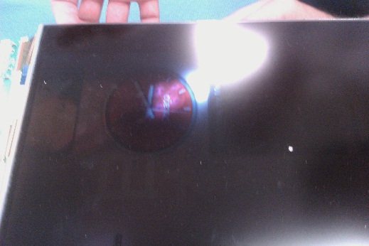
Here’s a picture of the cool FTIR effect we are able to achieve with our setup (more pictures coming soon)
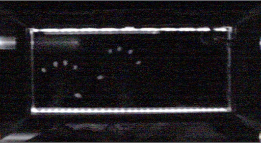
With all of the work that we’ve accomplished, we had a single accident that has pretty much halted all work on the table. We accidentally shorted out the power supply to our LCD matrix. We are frantically trying to find a replacement. Furthermore, when the power supply was working, we were only able to get the backlight to turn on for not more than 2 seconds at a time.
Once we get the power supply, our next step is to troubleshoot the backlight or just ensure that the LED matrix is working. *sigh*