Multi Input Sensing Table (MIST)
Project Charter
The most common methods for sensing touch input on multi-touch tables are capacitive, resistive, optical, force and acoustic techniques. Our approach will be to build a touch table with multiple sensors to collect optical, force and acoustic data. This data will be aggregated and processed to prove that multi-view sensing is more advantageous than single view sensing. In addition, we plan on implementing intel atom boards for sensor processing.
Multi-view sensing can provide additional useful data that is impossible for a single view to collect. For example, optical sensors alone are great for on-set detection and tracking single input or multi-input gestures. However, optical sensors cannot detect sound or pressure, which unfortunately limits the amount of interactions for a user. Neglecting these domains leads to poor user experience and reduces the usability of the table.
Project Overview
The goal of our project is to build a multi-touch table with multiple sensors to collect optical, force and acoustic data. Additional sensors allow for new and more natural forms of interactions.
Project Approach
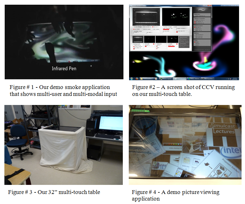
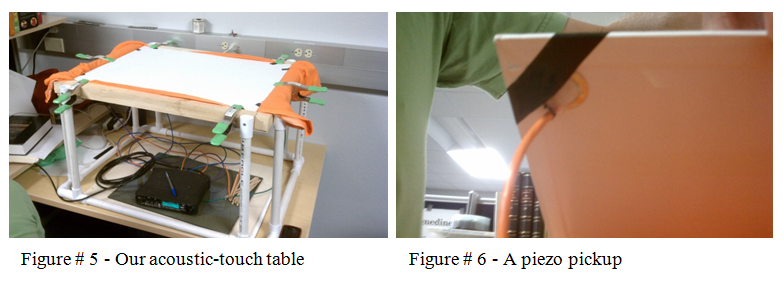
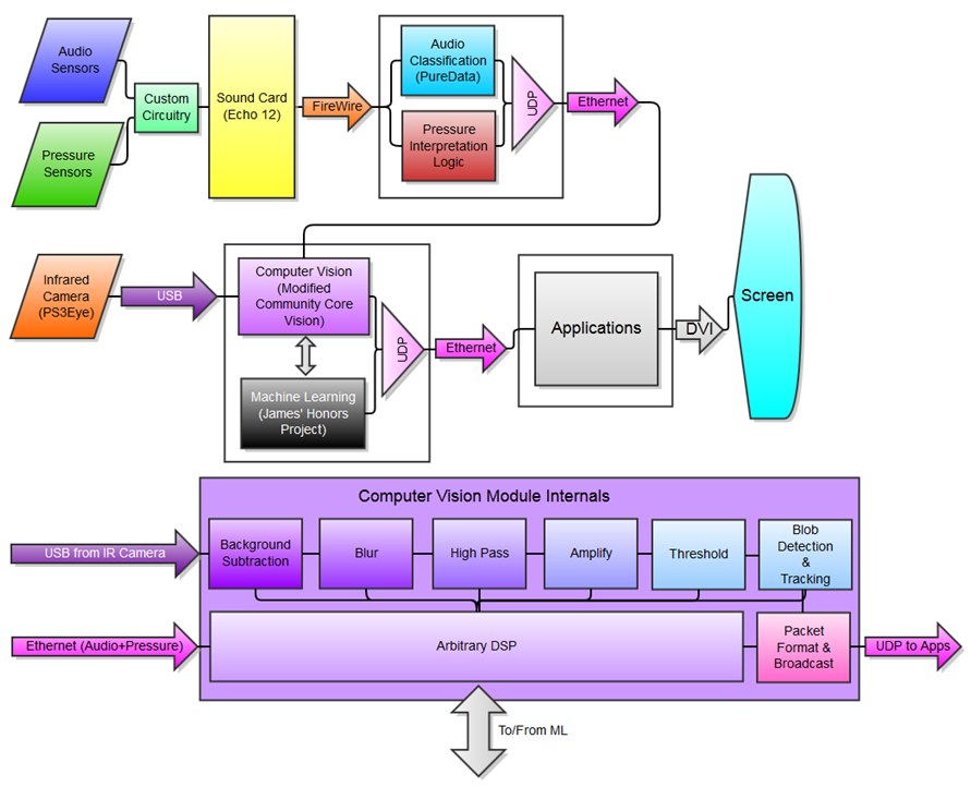
Last spring we built a Multi-touch table based on a 32” LCD TV (Figure 1, 3, 4) for the UCSD ENG 100L Simulcast Lectures project. The heart of our giant multi-touch table is a 32” 720p LCD TV. Our camera is a modified PS3 Eye, which provides 60 FPS @ 640×480 while having excellent sensitivity. To allow the PS3 eye to selectively sense infra-red light, we replaced the internal filter with an Infra-red band pass filter. To give the modified PS3 Eye to have something to sense, we placed infra-red LEDs in the frame of the table. We also placed white LED spotlights underneath the table in order to illuminate the screen. Using the CCV software (Figure 2) we can get the tell-tale white blobs of infra-red light to show up.
CCV processes all of the input from multi-touch table and then sends it out using TUIO (Tangible User Interface Object). The multi-touch drivers are called Multi-touch Vista and they can take input from multiple sources, but we are just using the TUIO input source from CCV. The drivers allow you to control windows through TUIO messages via and the windows multi-touch API. We’ve also used a couple of multi-touch demos from the Microsoft Touch Pack.
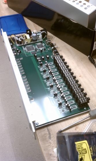
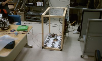
In addition to the FTIR multi-touch table we also have experimented with our new custom built acoustic table (Figure # 5). We built it toward the end of Fall 2011 in order to do preliminary testing and observations of the acoustic surface waves via piezo pickups (Figure # 6). Our observations so far have been better than expected. We have trained the timbre recognizer on 3 data types (pad, nail, knock) and each with only about 35 instances (tap sense used 300+ instances). The accuracy is pretty good. However, piezos may be limited to a certain degree of inaccuracy due to their biased frequency response. The good news is that it gets the pad right about 100% of the time. The nail and knock get misidentified, but this may be due to the clustering algorithm in timbreID. It may be worthwhile to try to improve on the learning mechanism of timbreID. It’s open source, so we can do what we want with it. It is also possible that a harder surface (i.e. glass or acrylic) will yield better results. We’ve only tested the piezos on a drawing canvas, although we also have maple, glass, and composite boards.
Project Objectives, Milestones and Major Deliverables
Our primary goal this quarter is to build a fully functioning sensing table. This entails the construction as well as the software architecture. We also plan on demonstrating the sensing capabilities of the table in demo applications. Our long term goals include data analysis and usability tests.
We would like to have our sensors installed and data ready for analysis as soon as possible. On the audio sensor side of things we will be purchasing equipment for acoustic signal processing i.e. something similar to the M-Audio Delta 1010 LT sound card. In addition, we plan on experimenting with various audio sampling hardware devices i.e. stethoscopes, microphone arrays, phono cartridges and piezos to determine if sound quality has an effect on input classification. We are also going to attempt to acquire X and Y coordinates from the audio inputs via time of arrival calculations. These coordinates can be cross checked with our FTIR optical coordinates.
On the optical side of things we are planning on partnering with Calit2. The multi-touch team in Calit2 has a very clean infra-red technique that uses microcontrollers for pulse width modulation to make the LEDs output at a higher amplitude and increase their useful lifetime. We want to apply this technique to our table.
In addition, we plan on distributing pressure or strain gauges around the corners to create a basic pressure sensitive surface. Accelerometers now have sample rates in the kilohertz and can detect vibrations as 3D vectors rather than single dimension intensity. They are not too expensive and are fairly easy to interface with using an Arduino microcontroller.
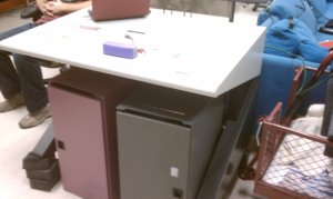
A decommissioned table in Calit2 might also come into play this quarter. It is about a meter wide and has a 16:9 aspect ratio. More importantly, it has an acrylic waveguide with mirrored edging and a lightbar. It is housed in grey melamine MDF sheets with an open front. It is kind of heavy, and takes up space when assembled, but it does have some foot room (an often neglected/sacrificed feature).
Once we’ve built the hardware we will begin to process the data and train our classifiers. We will also use the machine learning techniques previously outlined to combine all of the input views. Ideally our new table will solve all the current issues that we are facing. They are as follows:
- Soft and light touches are not detected
- People with small fingers find it difficult to use the table
- The surface of the table has too much friction
- The table cannot do unique user identification
- The table does not know how hard someone is pressing
- The table does not know what is touching it
- The table LEDs will not last as long as the proposed pulse width modulation LEDs.
Constraints, Risk and Feasibility
Problems can arise at every step of the project. Fortunately our group meets frequently and we tend to overcome problems with ease. Nonetheless, things like scope creep, budget growth, and deadline slips might be inevitable. We’re planning on working on many project paths in parallel, and we’re trying to shorten the critical path as much as possible. Ideally we’ll finish ahead of schedule, under budget and meet all of the feature specifications.
Risks include: delays on part deliveries, corrupted or incompatible software, driver support issues, lab and table construction sabotage.
Group Management
Project Manager
James McCloskey, Cognitive Science
Machine Learning Specialist
Alric Althoff, Cognitive Science
Multi-touch Specialists
Kevin Crossan, Computer Science
Roger Jennings, Electrical Engineering
Chris Lei, Computer Science
Computer Audio Specialist
David Medine, Computer Music
Project Advisers
Virginia de Sa, Cognitive Science
Ryan Kastner, Computer Science
Decisions are generally made by consensus. We communicate via email, meetings in the lab, and a google group discussion board. We will know when we’re off schedule based upon the rough timeline that we specified, and how will you deal with schedule slips by either solving the problem of adjusting the timeline.
We are each responsible for our task specific deliverables and milestones. James is responsible for hardware, table construction, and algorithm design. Chris and Alric will collaborate on system through application level software development.
James will produce the weekly group status reports.
Project Development
Project roles are outlined in the previous section.
The basis for the system and middleware programming is available in the free and open source Community Core Vision application. Modifications to this application will be made by the software development team.
Testing will be done incrementally using artificial data prior to table construction, and real table data once the table is conpleted.
Documentation will be written for specific applications once development is complete. Table instructions will be written once sensors have been integrated, and specifications for control signals sent from the table’s system and middleware have been finalized.
Building the table will be loosely similar to this guide: http://wiki.makerspace.ca/wiki/Multitouch
Projected Timeline / Schedule
Winter Quarter
- W1 – Team acquaintances and plan software achitecture
- W2 – Order components, construct table, and begin system level programming and application prototyping
- W3 – Construct table, ensure performance requirements for software are met
- W4 – Retrofit table, complete middleware and test applications
- W5 – Collect preliminary data
- W6 – Start development of data aggregation for multi-view processing
- W7 – Make second round of design modifications
- W8 – Finish algorithms
- W9 – Final debugging
- W10 – Final debugging
Spring Quarter
- W1 – Team acquaintances
- W2 – Usability test design
- W3 – First usability study
- W4 – Finish study & make design recommendations
- W5 – Implement design recommendations
- W6 – Second usability study
- W7 – Finish study & make design recommendations
- W8 – Implement design recommendations
- W9 – Finish Project
- W10 – Celebrate
Week 2
We have:
- ordered the pressure sensors
- finished the PCB design for the pressure sensors
- finished the first iteration of the pure data code for the audio sensors
- specified the external sound cards that we are purchasing
- re-designed our data process flow
- implemented some end user applications (without sensor controls integrated)
- tested the atom boards for feasibility
- tested the camera that we’re planning on using
- further disassembled the LCD screen from its housing
We need:
- determine a lighting scheme
- order materials to build the table frame
- send in the PCB designs
- test the pressure sensors once they arrive
- analyze the data from pure data
- run further tests on the atom boards
Week 3
We have:
- Recieved and tested the pressure sensors
- Ordered a mini PCI-e to firewire adaptor for the atom board
- Ordered 2x firwire cables
- Ordered 1x molex power splitter to power the firewire adaptor
- Working with different OpenFrameworks addons to build a GUI for a keyboard player application that will leverage our new pressure and audio classifier information.
- Working with current oFx ( Open frameworks ) add ons to sift through possible gesture libraries for handling gestures.
We need:
- To test the echo 12 with the atom board when the mini PCI-e to firewire comes in
- To install a better OS on the atom board
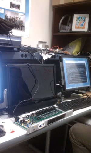
Here is the echo 12 sound card that we’re using for the sensor input:
Week 4
We Have:
- Recieved the mini PCI-e to firewire adaptor
- Installed Ubuntu
- Planned out the pressure sensor mappings for pitch, roll & z
We Need:
- To pick up the aluminium frame and make space in the lab for the table.
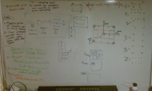
Here is our sketch set up and the atom board:
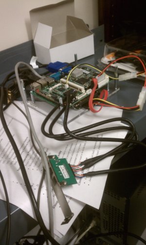
Milestone Report
Our original software milestones have been met and we are on schedule for data collection and refinement. We have written some basic applications which are able to receive and interpret commands from a modified version of Community Core Vision (CCV).
Week 5
The plan:
Week 6
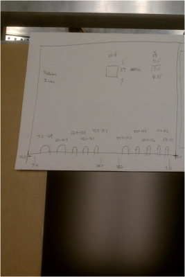
This has been a tough week. The PCB’s for the pressure and acoustic sensors haven’t been sent in yet. The atom board is still not working. And we were off by 1/16″ of an inch in our autocad file. We laser cut our acryllic and and the lcd panels ribbion cables don’t fit through the notches. We’re going to get it re cut soon.
Here is our autocad picture:

Week 7
This week went well. Roger ordered the PCB’s and we tested the circuits. The sensors are working. We also got a little side tracked and retrofitted the old table. We basically transplanted it into a new housing.
We finished it up and it looks great.
Final Milestone Report
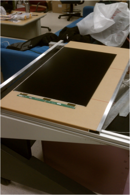
He have:
- We drilled and bolted the aluminum.
- We mounted the LCD screen and supporting circuit boards (temporary).
- We tested the screen and it turns on! (This means that we didn’t break anything).
We need:
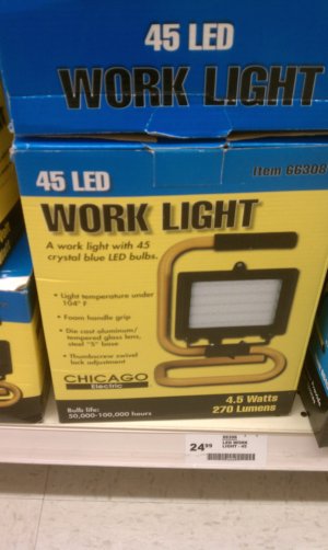
- To purchase additional lights
- Install the light bars and camera mount
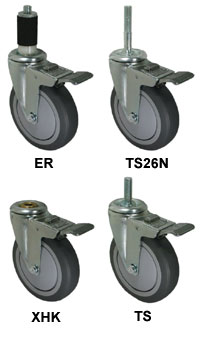
- purchase new casters
- install all of the sensors
- purchase and cut the 1/4″ cables
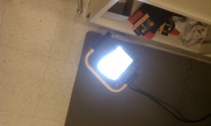
In terms of out project timeline/schedule we’re about 1.5 weeks behind schedule, but I’m very confident that we’ll finish before the end of the quarter. Here are some of the pictures from the old table retrofit and the new table build:
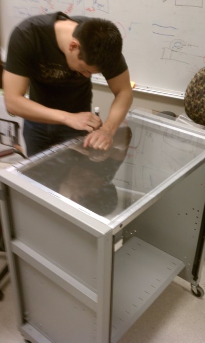
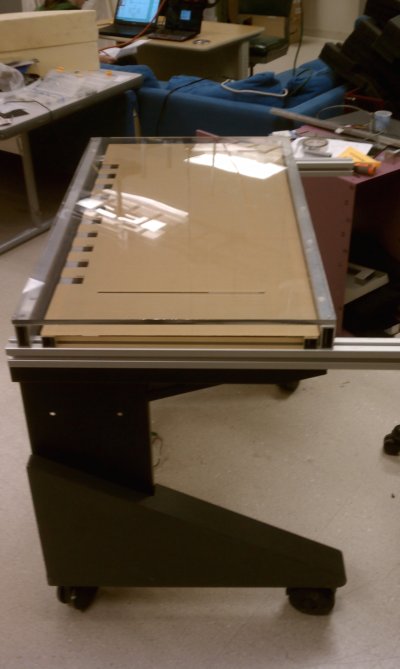
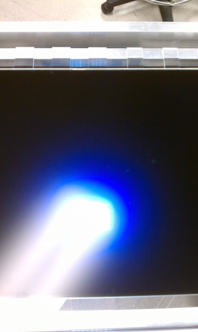
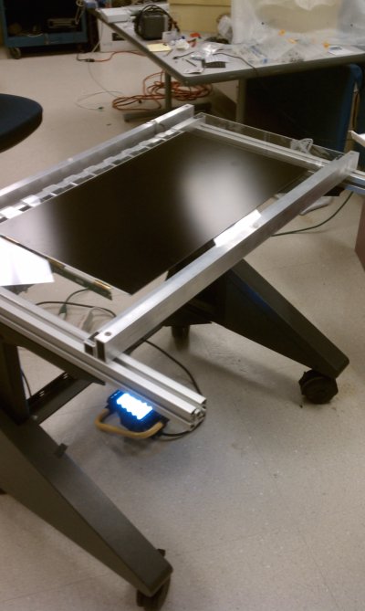
Basically we’re showing that the table turns on and that light is shining through.